In Class Activity #2
Have a TA check your work before moving on to the next exercise
Serial Plotter and Micro USB Pin
Serial Plotter
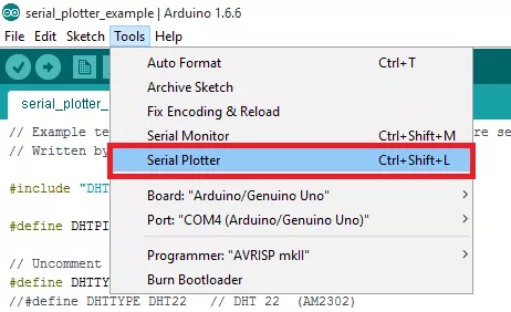
The Arduino Serial Plotter is a Tool that comes pre-installed with your Arduino IDE (version 1.6.6 and above) that takes incoming serial data and displays them in a plot. You are able to control the vertical axis, the Y-axis, and adjust its values as your serial data increases or decreases. The X-axis has 500 points and each tick of the axis is equal to an executed Serial.println() command.
How to open the Serial Plotter - Go to the Arduino IDE, “Tools” and Serial plotter (Ctrl+Shift+L)
Exercise 1
Run the code in the IDE with the Elegoo UNO board and joystick module and show the results in the serial plotter.
- Copy and paste the code below for each case and run in the IDE software
- Check the results in the serial monitor
int xPin = A0;
int xPin_Value = 0;
void setup() {
Serial.begin(9600);
pinMode(xPin, INPUT);
}
void loop() {
xPin_Value = analogRead(xPin);
Serial.println(xPin_Value);
delay(50);
}
--------------------------------------Code------------------------------------------------
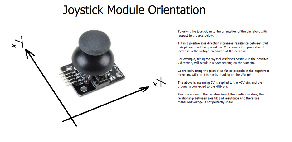
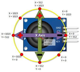
Exercise 1-a) When you move the joystick module to the left (+X, away from the pins) and right (-X, towards the pins) quickly, examine the graph on the Serial Plotter.
Question 1-a) What happened when you ran the code? (Include a screenshot of the Serial Plotter)
Question 1-a) What happened when you ran the code? (Include a screenshot of the Serial Plotter)
Exercise 1-b) When you hold briefly the joystick module of x axis to the left (+X, away from the pins) and then hold briefly to the right (-X, toward the pins), examine the graph on the Serial Plotter.
Question 1-b) What is the difference from the 1-a result?
Question 1-b) What is the difference from the 1-a result?
Exercise 2
Use Micro USB (Team task): Use the same code from Ex. 1
If you use the remote control for Project 2, you will need to extend the joystick module wire so that you can stand outside the arena. To extend the joystick module wire, you can use a longer wire or use other connectors like Micro USB pin connector (from your Arduino kit).
If you use the remote control for Project 2, you will need to extend the joystick module wire so that you can stand outside the arena. To extend the joystick module wire, you can use a longer wire or use other connectors like Micro USB pin connector (from your Arduino kit).
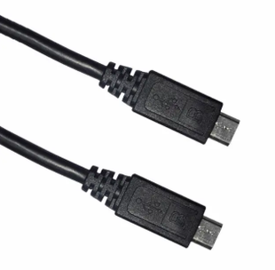
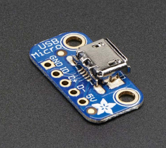
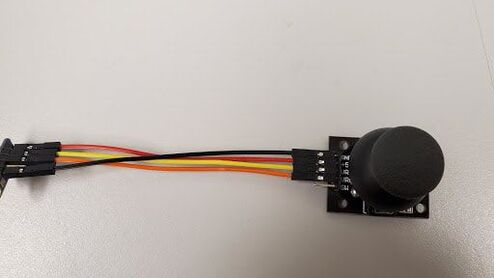
- In order to use the Micro USB pin, you need a Micro USB cable and a Micro USB Breakout board. Please see Figure 1.
- The micro USB Breakout board has five pins: GND, ID, D+, D-, 5V.
- You will connect the joystick module pins to the micro USB Breakout board.
|
|
Figure 1. (Left) Micro USB cable, (Right) Micro USB Breakout board
Step 1. Prepare Elegoo UNO board (1), Breadboard (1), Joystick module (1), Micro USB Breakout boards (2), Micro USB cable (1), female-female wires (4), jumper wires (6).
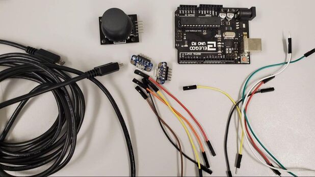
Figure 2. Components needed for Exercise 2.
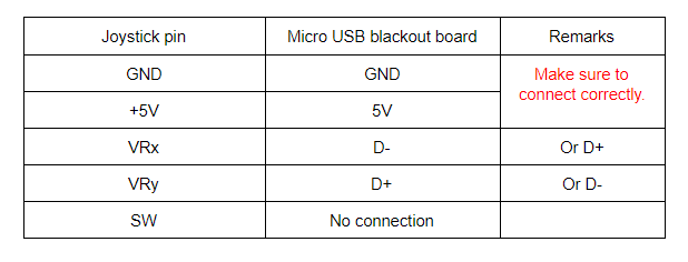
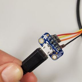
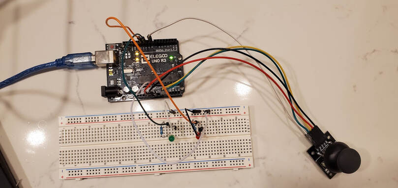
Step 2. Connect the USB Breakout board to the breadboard. Wiring is shown in Figure. 3 and described in Step 3 below.
Step 3. Wire the joystick to the other USB Breakout board, also shown in Figure 3.
Step 3. Wire the joystick to the other USB Breakout board, also shown in Figure 3.
- Because the ID pin of the Micro USB Breakout board does not read anything (it does nothing), we can read only the values from the four other pins. For this exercise, we will only read the values from the x-axis and y-axis.
|
|
Figure 3. Micro USB Breakout board cable connections.
Step 4. Connect other Micro USB Breakout board to the breadboard
Step 5. Connect the Micro USB Breakout board to the UNO board, shown in Figure 4.
Step 5. Connect the Micro USB Breakout board to the UNO board, shown in Figure 4.
- Connect D- to the UNO board’s analog pin A0
- Connect D+ to the UNO board’s analog pin A1
- Connect 5V pin (on the Micro USB Breakout board) to the UNO board’s power supply 5V
- Connect the GND pin to the UNO board’s ground pin GND.
- Hint: You can either directly connect the voltage from 5V or use the breadboard (+) power rail.
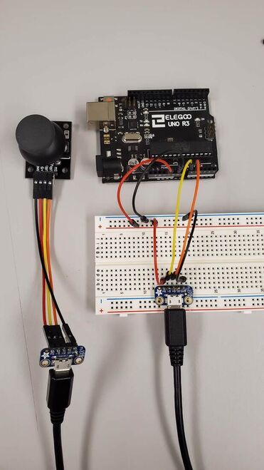
Figure 4. Wiring the USB Breakout board on the breadboard
Exercise 3
Redo Assignment #5 Ex. 4 using the Micro USB Breakout Boards and examine the values using the serial plotter. (Team task)
You will need to modify your circuit: Add components to Exercise 1 circuit.
You will need to modify your circuit: Add components to Exercise 1 circuit.
- When you move the joystick to move left (+X, away from the pins, xValue > 512), turn on the Red LED.
- When you move the joystick to move to the right (-X, towards the pins, xValue < 512), turn on the Green LED.
Step 1. To add one more LED, please prepare additional components: Green LED (1), 10kΩ resistor (1), Jumper wires (2)
Step 2. Add the wiring for the Green LED to the breadboard (Refer to Assignment #3)
Step 2. Add the wiring for the Green LED to the breadboard (Refer to Assignment #3)
- Connect GND to the (-) rail on your breadboard
- Connect the LED signal on the UNO board to the digital pin 10
- Be sure to include the 10KΩ resistor to avoid damaging your LED
Caution :
If you connect D- to the VRx, please make sure to connect to D- wire on A0.
If you connect D+ to the VRy, please make sure to connect to D+ wire on A1.
If you connect D- to the VRx, please make sure to connect to D- wire on A0.
If you connect D+ to the VRy, please make sure to connect to D+ wire on A1.
Step 3. Add a Global variable to the top of your code - Set Green LED as the variable LED_G = 10
Step 4. Coding: Set up - Set the pinMode for the pin LED_R as OUTPUT.
Step 5. Coding: loop (Red LED) - To change the control input, we need to modify if/else statement from Exercise 2.
Step 4. Coding: Set up - Set the pinMode for the pin LED_R as OUTPUT.
Step 5. Coding: loop (Red LED) - To change the control input, we need to modify if/else statement from Exercise 2.
- Write the code to turn on the Red LED when you move the joystick to left (+X, away from the pins)
- Hint: Use IF to check if the conditional statement is true.
- Hint: When the joystick is not moved, the X Value default may be 512. If not 512, use your default value instead. My default was 503, so I will use 503.
- Hint: When you move the joystick to the left (+X, away from the pins), the value is greater than your default value, i.e. more than 512.
- Hint: LED is a digital signal. Remember, use digitalWrite.
- Hint: To turn on the LED, set the Red LED to HIGH.
- (The default value could be different by the sensor)
- If the joystick moves to the left (+X, away from the pins), then turn on the Red LED.
- Hint: you should use IF to check if this first conditional is true.
- Hint: LED is a digital signal. Remember, use digitalWrite.
- If the joystick is moved to the right (-X, toward the pins), then turn on the Green LED.
- Hint: you can use ELSEIF to check if this second conditional is true.
- Hint: LED is a digital signal. Remember, use digitalWrite.
- Hint: To turn on the LED, set the Green LED to HIGH.
- Otherwise, if the joystick does not move to the left or to the right, then we want both of the LEDs off. This is a third conditional statement.
- Hint: You can use the “else” statement for the third conditional statement.
- Hint: LED is a digital signal. Remember, use digitalWrite.
- Hint: To turn off the LEDs, then set both LED_R and LED_G as LOW
- Hint: You can use the “else” statement for the third conditional statement.
