Assignment #3
Now that we have acquired the ELEGOO kits, we can start to work with the physical Arduino IDE. For the first half of this assignment, we’ll practice utilizing ports, the serial monitor, wiring the circuit, and running the code we wrote in Assignments #1 and #2.
Installing Arduino
In order to access our Arduino, we have to use the Arduino IDE (integrated development environment) instead of TinkerCad. Visit the link below to get started.
If you’re running Windows, it is advisable to use the ZIP non-admin install to avoid any errors. If you’re running Mac or Linux, select the appropriate option from the menu as shown. Clicking any of these will take you to a page which asks for a suggested donation. You can select “Just Download” to bypass this.
From here, you can open up the downloaded folder. Select the application, and unzip when prompted. This may take a while. When it’s finished, you should be able to open the application by selecting the executable.
Once you have the IDE open, you’ll need to plug in the Arduino and select the port. You must ALWAYS do this when you plug in the Arduino, or it will give you an error (see below):
Notice how before I’ve plugged in the Arduino it shows the red text and does not change. After I plug in the Arduino and go to Tools > Port > and select the one that says “Arduino/Genuino,” I can successfully compile (indicated by the green bar in the bottom right).
Exercises
Exercise 1: Serial Monitor
- Plug your arduino into the computer with the USB cable
- Select Arduino/Genuino from the ports list
- Copy and paste in your code from Assignment 1, Exercise 5 ("Hello World" + Timer in seconds)
- Run it and observe the output in the Serial Monitor
Short Answer:
- Try changing the baud (bottom right corner of the Serial monitor). What happens? Copy and paste an example output when the baud is changed. Why do you get this output?
Exercise 1: Output
Exercise 2: LED Always On
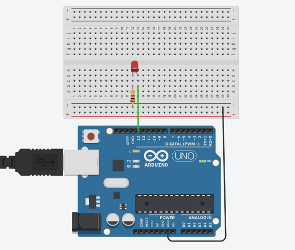
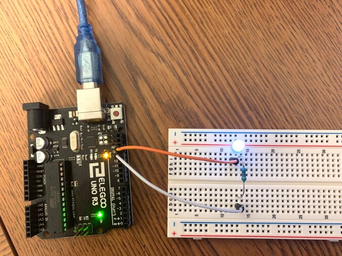
Now, we want to wire up the LED and reproduce Exercise 1 from Assignment #2.
- Connect GND to the (-) rail on your breadboard
- Wire the LED as shown below (use male-male jumper cables)
- Be sure to include the 10KΩ resistor to avoid damaging your LED
- Run your code from Exercise 1
- Green light on the UNO board should be on
Exercise 2: Output
Exercise 3: LED Blinking
Now, we want to reproduce Exercise 3 from Assignment #2. The circuit will be the same, but now run your code from Exercise 3.
- Connect GND to the (-) rail on your breadboard
- Wire the LED as shown below (use male-male jumper cables)
- Be sure to include the 10KΩ resistor to avoid damaging your LED
- Run your code from Exercise 3
- The green light on the UNO should be on

Exercise 3: Output
Exercise 4: Pushbutton
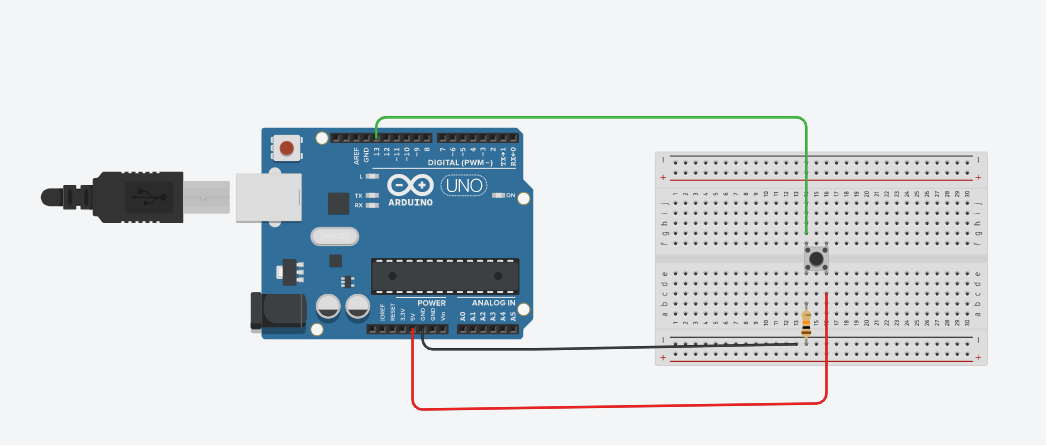
For this exercise, we want to wire the pushbutton to the Arduino and read the pushbutton state in the Serial monitor as what we did in Exercise 4 of Assignment #2.
- Connect GND to the (-) rail on your breadboard
- Wire the pushbutton to the Arduino as shown below (use male-male jumper cables)
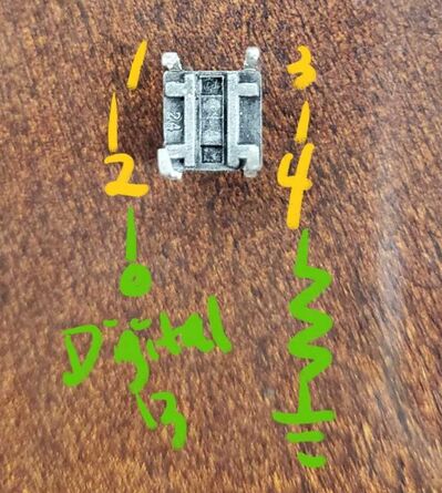
- Note: We suggest placing the pushbutton in the center of the board as shown in the wiring diagram because you will notice it only fits easily in one orientation. You could place it anywhere else, but you'll have to keep track of the orientation. See figure with pins labeled 1-4.
- Be sure to include the 10KΩ resistor to avoid damaging your pushbutton
- Run your code from Exercise 4
- Hint : 2 legs on the one push button are connected each other. If your push button does not work well even with correct wiring, please rotate 90 degree to connection. This shouldn't be a problem though if you place it at the center of the board since it will only really fit in one orientation at the center.
- Photo below shows the bottom side of the push button : 1 (or 3) need to connect to the digital 13 pin and 3 (or 4) pin need to connect to the resistor.
Exercise 4: Output
Short Answer
- Try changing the baud (bottom right corner of the Serial monitor). What happens?
- What is the difference between these two buttons? What does each one do?

Submitting the Assignment
For each of your codes, take screenshots of the IDE, Serial monitor, and photos of your Arduino/breadboard. Compile these into a Word document using the template we provide, save as PDF, and submit as a PDF to Blackboard. Include your public project link.
