In Class Activity #1
Individual Assignment: Wiring a Photoresistor
We’ll begin by wiring a single photoresistor, and reading the output in the Serial monitor. Wire the photoresistor as shown below:
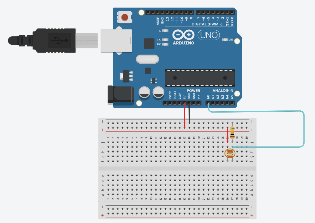
Don’t forget to include the 1KΩ resistor to avoid damaging the photoresistor. Declare pin 0 as input, use analogRead() to obtain data from the photoresistor, and write the data to the Serial monitor using Serial.println(). Try covering the photoresistor and observe the change in the output reading.
Short Answer:
(We won’t be collecting your responses, but you’ll need this information for later, so it might be helpful to write it down.) Check in with a TA before moving on to the next exercise.
Short Answer:
- What is the value when the photoresistor is fully exposed to the ambient lighting of the room?
- What is the value when you cover the photoresistor?
(We won’t be collecting your responses, but you’ll need this information for later, so it might be helpful to write it down.) Check in with a TA before moving on to the next exercise.
Team Work: Wiring the LCD and Photoresistors
Once you have completed the individual assignment, we can switch over to teamwork. Combine two of your photoresistor rigs onto a single board to look like the rig below:
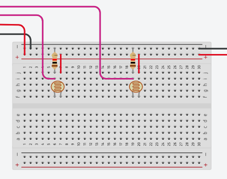
Be sure to use a 1K resistor for each photoresistor. Each pink wire (our kit doesn’t include pink, so use a different color) should go to the analog pins A0 and A1 respectively. Wire up power and ground from the board as shown on the left. Add an additional black and red wire to the right of your breadboard- we’ll hook up the provided LCD rig to this in the next step.
PLEASE NOTE: These LCD rigs belong to the 250 lab. Return them in the same state they were given to you at the end of class, with all original wiring intact.
PLEASE NOTE: These LCD rigs belong to the 250 lab. Return them in the same state they were given to you at the end of class, with all original wiring intact.
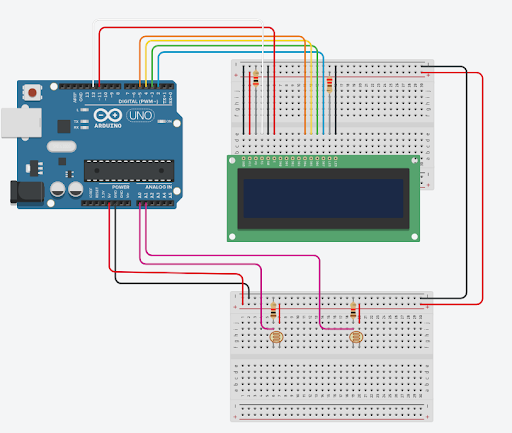
As shown above, you should wire the power and ground from the Photoresistor board up to the power and ground for the LCD board. Hook up:
- LCD RS pin to digital pin 12
- LCD Enable pin to digital pin 11
- LCD D4 pin to digital pin 5
- LCD D5 pin to digital pin 4
- LCD D6 pin to digital pin 3
- LCD D7 pin to digital pin 2
Step 1: LCD Setup
- Import the liquid crystal package
- Declare your lcd object using the following syntax, where the pins are replaced by their actual pin numbers

- In the setup, begin the lcd as 16 columns and 2 rows, with the syntax lcd.begin(columns, rows)
- Only once, use lcd.print to print “Hello World” to the LCD
- Have a TA check your work before moving on to the next exercise
Step 1: Output
Step 2: Moving the cursor
Now, let’s write the elapsed time on the second line of the LCD. In the loop of the code you’ve already written:
- Use lcd.setCursor(column, row), to go to the first column (index 0), and the second row (index 1)
- Use lcd.print() to print the elapsed time in milliseconds (hint: use millis())
- Delay 1 second
- Erase everything using lcd.clear() (note that this resets the cursor position)
- Print hello world again as you did in the setup
- Have a TA check your work before moving on to the next exercise
Step 3: Reading the Output from the Photoresistors
Refer to the code you wrote for photoresistor readout. We would like to write the current readout from each photoresistor as shown below. Use the cursor tool to move to the second line for the second photoresistor. As a team, try to achieve the output shown below. If you need a hint, consult a TA.
Step 3: Output