In Class Activity #1
Multimeter
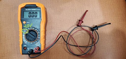
A multimeter or a multitester, also known as a DMM if it is a Digital MultiMeter, is an electronic measuring instrument that combines several measurement functions in one unit. A typical multimeter can measure voltage V, current I, and resistance R (these are related by Ohm's law,V=IR). Analog multimeters use a microammeter with a moving pointer to display readings. We will use a DMM in class.
Team Work: Check Voltage with a Multimeter
Complete Ex. 1 from Arduino Assignment #3 and download the Arduino software so we will be able to run the code. You can copy over your code from Ex. 1 from Assignment #2. We will check the voltage with the multimeter for the circuit we are creating for Ex. 2 from Assignment #3.
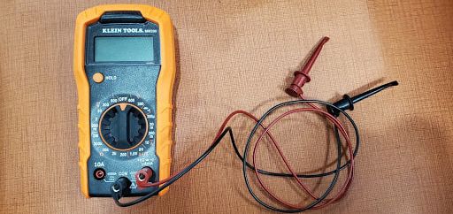
Step 1: Prepare the Multimeter
- Prepare multimeter 1, Red jumper wire 1, Black jumper wire 1
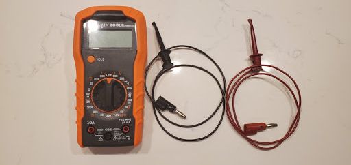
- Connect Black jumper wire on the “COM” port
- Connect Red jumper wire on the right port under the “+VΩ…symbols”
Step 2: Wire up the LED
Now, we want to wire up the LED the same way as we did in TinkerCad for the LED to turn on. You already have the code prepared in Ex. 1 of Assignment #2.
- Hint: If you do not know how to get started, let’s first watch a video about the hardware you are going to use.
- Hint: If you do not know how to get started, let’s first watch a video about the hardware you are going to use.
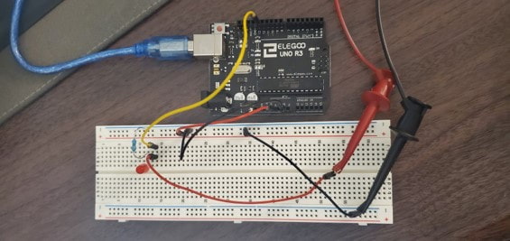
- Prepare : UNO(1), Blue connector(1) for connecting between computer and UNO board, Breadboard(1), LED(1), 10kΩ Resistor(1), jumper wires (total 5: Red(2), Black(2), and Yellow(1)).
- Connect GND to the (-) rail column on your breadboard.
- Wire the LED as shown below (use male-male jumper wires)
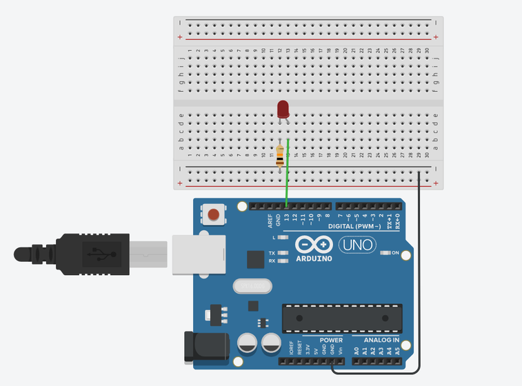
- Be sure to connect the 10kΩ resistor to avoid damaging your LED
- Connect the UNO to the computer with a USB Cable
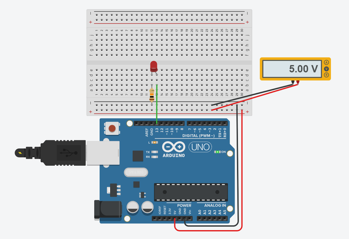
Step 3. Use the multimeter to check the voltage in the circuit before running the code
Question 1. What is the voltage before running the code? |
Output
We can also use a multimeter to measure the voltage across the breadboard on TinkerCad as shown below. If you still don't know how to use the multimeter, click here for a demonstration video. The output should be ~5V and will be less than 5V (recall: 5V is the power supply provided by the UNO board and we won't get exactly 5 V).
Step 4. Remove the cable from the computer to prevent hot-swap
Hot swapping is changing components without stopping or shutting down the system. To prevent the damage, it is better to turn off the power or unplug the power source before making any changes to the circuit.
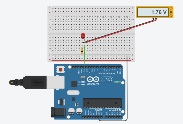
Step 5. Check the voltage drop across the LED after running the code
- Reconnect the Arduino UNO board to the computer and check the green light on the UNO board to ensure the connection.
- Connect two jumper wires(Red, Black) in the breadboard before the LED (Red) and - (Black), just like the photo below.
- Run your code from Exercise 1, Assignment #2. The LED bulb should be on.
Output
Question 2. What is the voltage drop across the LED? Follow the diagram below to check the voltage before/after the LED.
Hint: The voltage drop across the LED is ~1.5 V. It can be different for the kits overall, small differences should be expected.
Hint: We have used a RED LED in the diagram. If you use a different color, you should expect different voltages!
Hint: The voltage drop across the LED is ~1.5 V. It can be different for the kits overall, small differences should be expected.
Hint: We have used a RED LED in the diagram. If you use a different color, you should expect different voltages!
Output
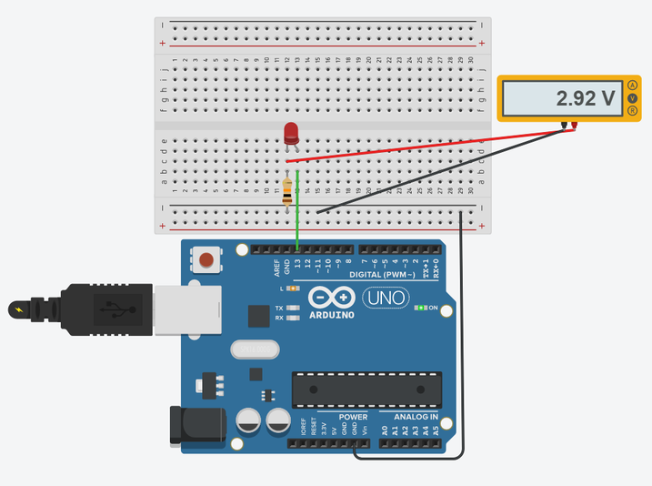
Question 3. What is the voltage drop across the resistor? Use the diagram below to find the voltage before/after the resistor.
Hint: It can be different for the kits, small differences are expected.
Hint: It can be different for the kits, small differences are expected.
Question 4. Let’s add up voltages across each the LED and the resistor. What do you get?
Output
You should get about the same as the input to the breadboard that you measured, about 5V, 1.76+2.92 = 4.68 V
Hint: The voltage should be the sum of the LED and resistor voltages.
Hint: The voltage should be the sum of the LED and resistor voltages.
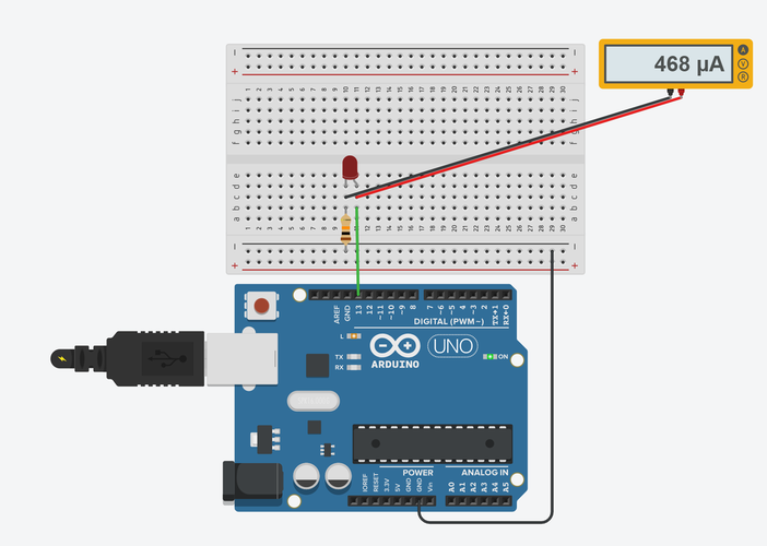
Step 6. Check the current
- Move multimeter dial to 20mA
- Check the current across LED
- You can also do this in TinkerCad, just like you did for voltage.
Output
Question 5. What is the current across the LED? Use the diagram below to measure the current.