Assignment #4
Joystick Module - A joystick is an input device consisting of a stick that pivots on a base and reports its angle or direction to the device it is controlling. Joysticks are often used to control video games, and usually have one or more push-buttons whose state can also be read by the computer. Joysticks are also used for controlling machines such as cranes, trucks, underwater unmanned vehicles, wheelchairs, surveillance cameras, and zero turning radius lawnmowers. Miniature finger-operated joysticks have been adopted as input devices for smaller electronic equipment such as mobile phones. Be sure to watch these videos before proceeding with the assignment.
Now, Let’s use the Arduino to read the joystick signal (analog) following the videos step by step.
Step 1: Preparation
1 Elegoo UNO, 1 breadboard, 1 USB cable, 5 female-male jumper wires, 1 Joystick module, 1 Joystick hat
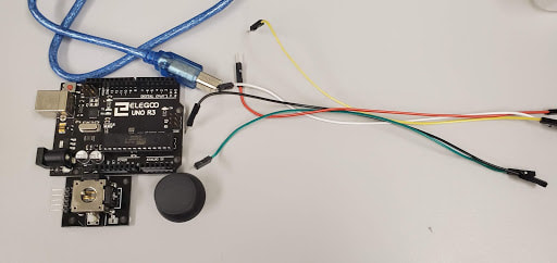
Step 2: Wiring
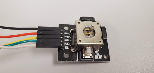
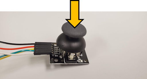
- Connect the hat on the joystick. It can only fit in one orientation (examine the underside).
- Connect GND in the joystick module using a female-male jumper wire to GND in the UNO.
- Connect 5V+ in the joystick module using a female-male jumper wire to 5V in the UNO.
- Connect VRx in the joystick module using a female-male jumper wire to the analog pin A0 in the UNO.
- Connect VRy in the joystick module to the analog pin A1 in the UNO.
- Connect SW in the joystick module to the digital pin 8 in the UNO.
- Ensure all pin connections are tight. Otherwise, the circuit will not be complete and it will not work.
|
|
Step 3: Coding - Declare Variables
- Declare a new variable called “xPin” and set it to the analog pin A0.
- Declare a new variable called “yPin” and set it to the analog pin A1.
- Declare a new variable called “KeyPin” and set it to be the digital pin 8.
- Declare a new variable called "xPin_read"
- Declare a new variable called "yPin_read"
- Declare a new variable called "KeyPin_read"
Step 4: Coding - Setup
- Set the “KeyPin” mode as INPUT_PULLUP
- Write the KeyPin output as HIGH (only need to do this once!)
- To communicate, begin the Serial communication with a baud rate of 9600
- Show the results in the Serial Monitor
Step 5: Display Results in the Serial Monitor
In the joystick module, there are two different types of signals.
1) For the x and y-axis, the signals will be analog
2) For the z-axis (like the push button), the signal will be digital.
Hint: To read an analog signal, you need to use analogRead.
Hint: To read a digital signal, you need to use digitalRead.
1) For the x and y-axis, the signals will be analog
2) For the z-axis (like the push button), the signal will be digital.
Hint: To read an analog signal, you need to use analogRead.
Hint: To read a digital signal, you need to use digitalRead.
- To display the results repeatedly, the code should be written in the loop
- In order to verify the signals, let’s print “X=” before reading the xPin value so we can understand what it is when it gets printed to the Serial Monitor.
- Read the x-axis value(analog pin A0) and store this value as the variable xPin_read.
- Print the “xPin_read” value to the Serial Monitor.
- Again, print “|Y=” before reading the yPin value to prevent confusion.
- Read the y-axis value(analog pin A1) and store this value as the variable yPin_read.
- Print the “yPin_read” value to the Serial Monitor.
- Again, print “|Z=” before reading the KeyPin value to prevent confusion.
- Read the z-axis value(digital pin 8) and store this value as the variable KeyPin_read
- Print the “KeyPin_read” value to the Serial Monitor.
- Add in a delay of 500 milliseconds
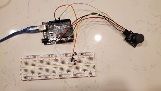
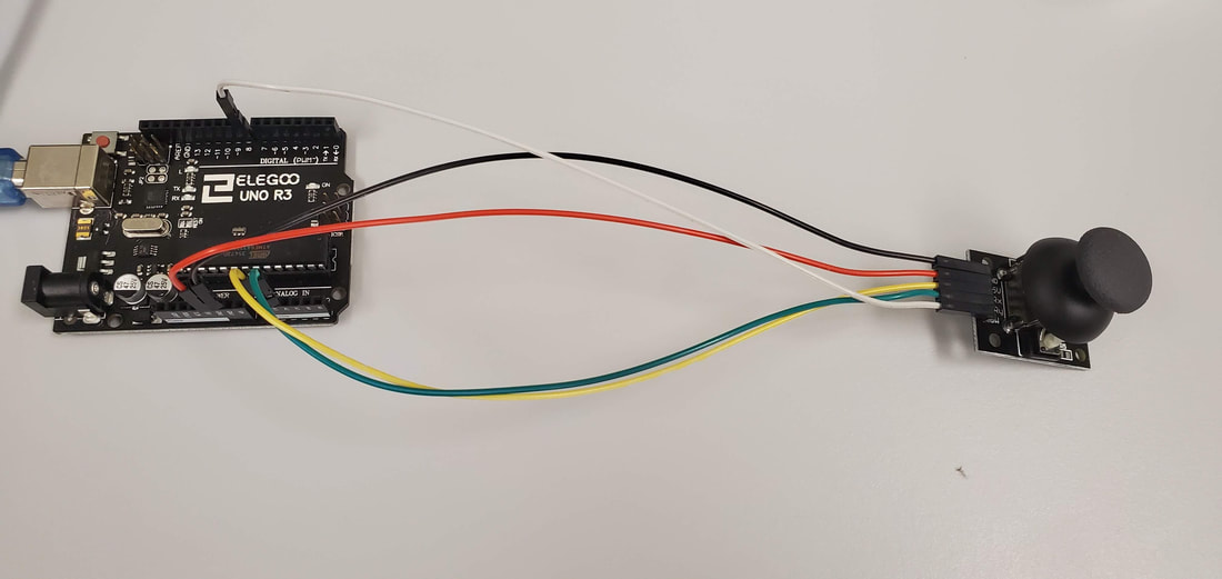
Take a picture of your joystick circuit and attach it on the document.

Question 1:
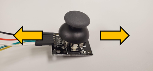
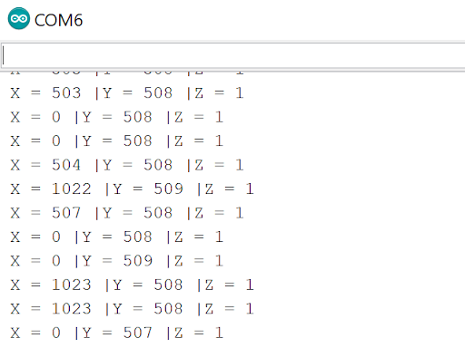
Get the x-axis signal on the serial monitor when you move the joystick on the x-axis.
(You do not need to show exact same values from the output. You can capture the screen when the X values are changed)
Hint : The initial value could be different. If you can see the change of value when you move your joystick, It is totally fine.
(Every sensors could have different default)
(You do not need to show exact same values from the output. You can capture the screen when the X values are changed)
Hint : The initial value could be different. If you can see the change of value when you move your joystick, It is totally fine.
(Every sensors could have different default)
Output: Show the change of x value
|
|
Hint: Y value also will be changed during moving. Don’t worry about y-value.
Question 2:
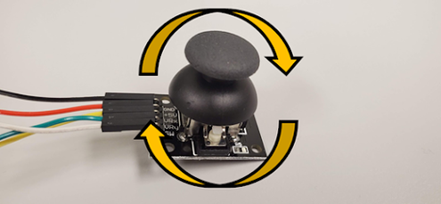
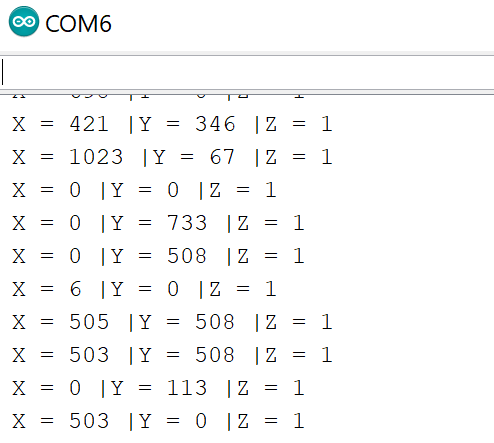
Get the X and Y axis values on the Serial Monitor when you move the joystick in xy axis.
Output: Show the change of x and y values
|
|
Question 3:
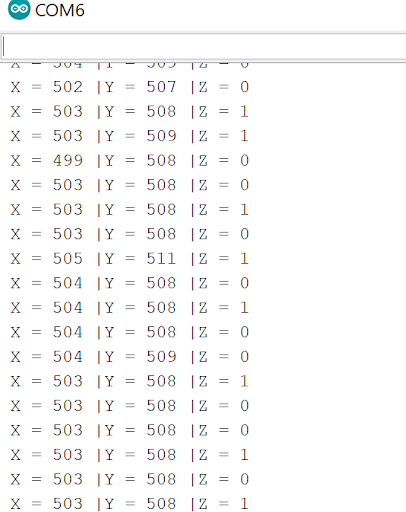
Get the Z signal on the Serial Monitor when you push the joystick in the z-axis.
Output: Show the change of z values
|
|
Short Answer
- When the joystick is moved 45 degree to the right and upward on the side of the joystick without the pins, what is the reading?
- When the z-axis is pressed down, what is the reading?
Submitting the Assignment
- For this assignment, take a picture of the joystick circuit. For each of questions, take screenshots of the IDE, and outputs in the serial monitor. Compile these into a Word document using the template we provide, and submit as a PDF.
- Late penalty: This assignment is due Friday at 6 PM. If submitted late, and less than 24 hours from the due date, 10% will be deducted from the total score, 20% will be deducted if between 24-48 hours etc. Be sure to check your submission on Blackboard to ensure you submitted the correct file after you click SUBMIT.
